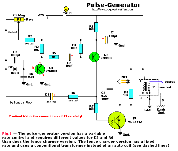
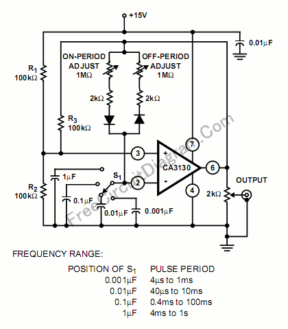
Complete avalanche pulse generator circuit Circuit Diagram Although I own a somewhat expensive commercial function generator, I find that this pulse generator is the one I reach for most of the time. The generator is fairly easy to build and uses a straightforward design. It requires six integrated circuits and two transistors. In addition, you will need a power supply of 15 volts at 200 mA. I have a DC supply (5 V) to turn some circuit on and in that circuit there is a module which uses a specific mechanism (i.e. a 2 seconds width high pulse) to turn on (even if a supply is connected, that module will turn on only by this mechanism i.e 2 seconds pulse). So I want to generate a pulse (high) of 2 seconds when that DC supply is Hello! For my very first instructable I wanted to show how to build a pulse generator circuit using the ever so popular 555 timer chip. This is a very simple, yet very important, circuit to build and understand. It provides a great introduction into integrated circuits and the 555 chip finds its way into many more sophisticated circuits.

In this video you will learn how to make a pulse/wave generator with varying frequency with help NE555 timer IC.For more information and circuit check the ar

Building a Pulse Generator Circuit Diagram
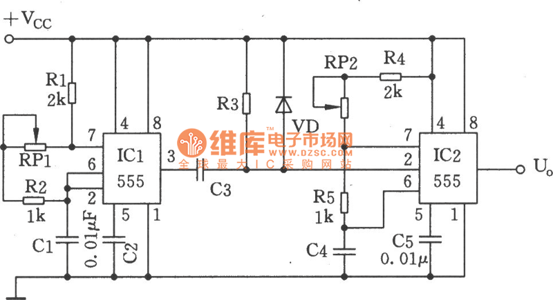
The following session documents the design and fabrication of a TTL Pulse Generator for this driver circuitry, with emphasis placed on design considerations and application techniques. First segment of the pulse generator is a classic astable multivibrator circuit built around the ubiquitous NE555 timer chip (IC1).

In the circuit above, we see a 555 timer configured as an astable oscillator. The 555 timer will generate the pulse width modulation signal at a specific duty cycle and switch the MOSFET transistor Q1. The MOSFET transistor in this circuit is the IRF540 MOSFET transistor. These pulse generator circuits—a.k.a. an astable multivibrator oscillator circuit—employ a 555 timer IC, NE555 or LM555, in its astable (free-running) mode. These types of circuits are often paired up with digital logic circuits. The 555 timer IC is also very popular and simple to use, with a small eight-pin package and a supply voltage range of 4.5V to 16V.

How to generate a single pulse using RC circuit from a fixed DC supply ... Circuit Diagram
1. To design and simulate the pulse generator circuit that can transmit data at high frequency (0-900MHz) with the UWB technology application. 2. To apply knowledge and hands-on experiences that independently working to the project with the guidance of a supervisor. 3. To simulate and design circuit with Spectre software (Virtuoso Analog Design Pulse Circuits - Miller Sweep Generator. The transistor Miller time base generator circuit is the popular Miller integrator circuit that produces a sweep waveform. This is mostly used in horizontal deflection circuits. Let us try to understand the construction and working of a Miller time base generator circuit. Construction of Miller Sweep
