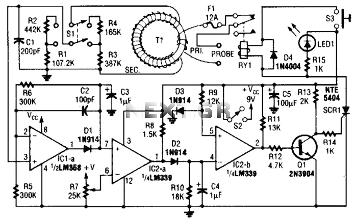
DC Electronic Fuse Circuit Construction Working Circuit Diagram The given electronic fuse circuit is based on a poly-fuse application, which is a re-settable fuse by itself. Electronic fuse circuit Fig. 1: Electronic fuse Circuit operation. Initially, when the circuit is powered, silicon-controlled rectifier SCR1 is 'off.' Relay RL1 energizes through the polyfuse and the load is connected through the
The complete circuit diagram for an electronic fuse circuit is shown below. As shown in the circuit, it involves only few circuits and hence it is easy to construct and implement into our designs. Here the circuit is constructed to monitor the operating current of a motor (LOAD), which operates on 12V. You can replace the load with any circuit

Electronic Dc Fuse Circuit Diagram
Electronic Fuse Schematic Diagram . Current fuse can be set to the maximum output current (about 10 mA) up to the maximum allowable current of the transistor T1 (BUZ11 - 20A). the fuse is power supply of +5 V with integrated stabilizer 7805, +5 V voltage reference voltage and therefore stability is important to determine the accuracy of the
This rather defeats the purpose of a very fast electronic fuse. Some circuits are more amenable to applying a delay than others. It's easy with the Figure 5.1.1 circuit (see Figure 5.1.2), but harder (and less predictable) with the circuits shown in Figures 5.1.3, 5.1.4 and 5.1.5. including but not limited to all text and diagrams, is the

Detailed Circuit Diagram Available
A basic electronic fuse circuit diagram is composed of symbols representing the components of the circuit, including the switch, the fuse, the capacitors, the inductors and the resistors. The purpose of each component is also represented by its own symbol. As such, understanding the symbols used in the diagrams is essential for readers to